

CONSTRUCTION
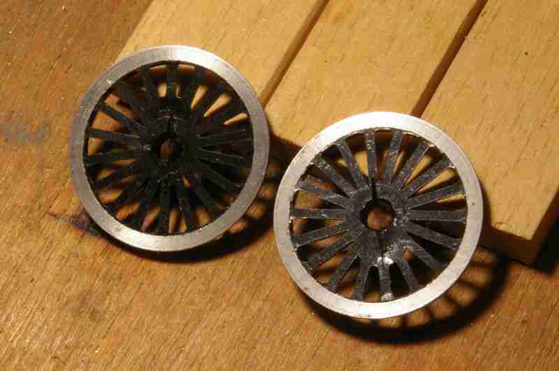 At this point, the electrics need to be dealt with. To get the current from the wheel tyres to the axles I use 6th phosphor bronze wire. Copper can be used, but it’s very soft, and is inclined to break when fitting the wheels to the axles. The two photos show, firstly shallow grooves cut into two of the spokes (opposite each other) to accommodate the wire, and to provide a slight bend into the axle hole (rather than a sharp right angle), and secondly one of the wires held in place with blu-the tyre. The trick is to make sure that that tyre and the wire are clean, to use a little liquid flux, and a reasonably large iron (25W) to get the heat in quickly without damaging the plastic moulding. Virtually all of the locos I have built have used Sharman wheels, with fairly soft moulded centres, and I have not had any problems using just two wires. However, a more recent experience with Gibson wheels (which use a slightly harder compound) shows that these are not quite so forgiving, and the use of just two wires can cause ‘wheel wobble’ when fitted to the axles. Three wires at approximately 120deg seems to fix this problem.
 The final task for the wheels is to cut the wire to length and remove all traces of flux and any excess solder from the back of the flange so that nothing catches on point blades and check rails etc.
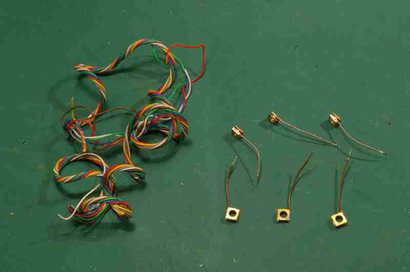 To get the current from the bearings to the frames, and from the frames to the motor, I use fine multi-
The last stage is to re-
It’s worth rounding off the ends of the axles a little bit, so that’s there’s less likelihood of cutting the wires when the axles are pushed home.
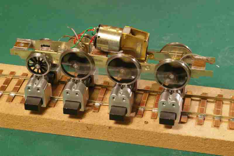 In the past I have used the tried and tested method of aligning spokes visually, followed by trial and error. I usually start with the driven axle, and then add the coupling rods, but only fitting the crankpin bushes to the driven axle and an adjacent one, adjusting that axle, and then fitting the third pair of bushes, and adjusting the third axle. Hopefully this should give a freely running chassis. The photo shows the first test on a Bachrus rolling road system. It works!
This method has worked for me for many years, but I have now purchased a GW Models wheel quartering jig (Scaleforum 2017). This is the most beautifully simple quartering device I have seen, and which has made fitting wheels much quicker, easier and more accurate. There is more detail here.